TOS Romulan BoP

For all other scales including 1/72, 1/537, 1/650 and Studio.
Post Reply
User avatar
MSgtUSAFRet
Can-Do Captain
Can-Do Captain
Posts: 531
Joined: Wed Jun 15, 2016 5:49 pm
Location: Houston, TX

TOS Romulan BoP

Post by MSgtUSAFRet »

Hey Guys!

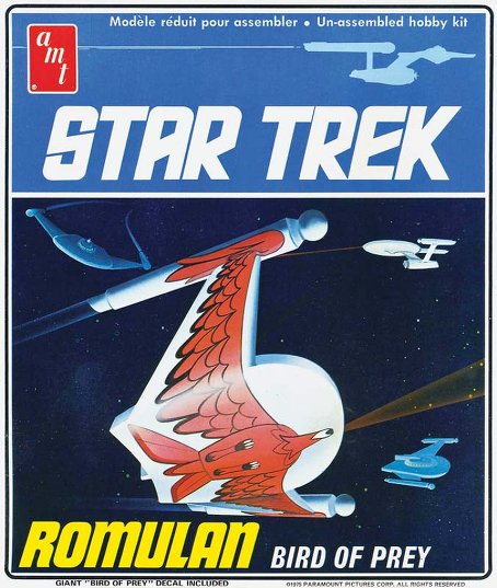
I'm kinda new to this forum so I thought I would start out with a "simple" build currently on the bench. I am building a AMT 1/650 TOS Romulan BOP. This will continue my infatuation with ST:TOS but, after having build one AMT/ERTL 18" TOS Enterprise and restored one 1974 TOS Enterprise, I am ready to build something a bit different from the Federation! :D

Image

I chose this kit for some specific reasons: 1) the kit is a relatively easy build 2) it is a TOS era kit 3) this will be my first attempt at lighting a kit! I hope to not have to focus so much on the build as I can focus on the lighting. The aspect that is a bit intimidating is the lighting portion. I am a “business major” by education and very few dental patients (read here NONE!) ask for a lighted prosthesis so I am a virtual newb to this part of the community and to electronics itself. So I may be asking a lot of questions on lighting in the Modeler’s Question board. Inspired by Steve’s (trekkriffic) build, I plan to add gridlines and impulse exhaust ports and a little more detail than what may be considered canon.

My son picked up a TOS Romulan BOP Diamond Select display model (Yes, I have infected by children with a love of all things Star Trek!) with lights and sound, so I will be using it as a 3-D guide.
In comparing the two, I immediately see glaring differences. Looking at it from the Dorsal view, the stern of the Hull is missing some contour. I would like to add the missing contour.

Image20160503_192243

Jay Denis , a builder on Culttvman.com, provides a partial list of the AMT models inaccuracies:
1. Engine nacelle forward detail – AMT designed it with a full sphere instead of a half sphere
2. Engine nacelle rear detail – should be smaller outside circumference than the rest of the engine
3. Main hull sides – The kit’s hull sides are vertical and the studio model’s hull sides angle outward from bottom to top at approximately 25-30 degrees.
4. Top superstructure height – too tall
5. The Ventral and Dorsal stern primary hull is convex instead of concave
6. The Dorsal Fin is 2X’s as thick as the Studio Model’s
7. Plasma weapon emitter – This part was included in Round2’s reissue of the model

Admittedly this is not an exhaustive list – it is a start at some modifications to make it closer to what we all have seen on the screen.

I will be using Mark McMaster’s blueprints as guidance during the build. They are freely available at cygnus-x1.net.

Here are some pics on my plan for gridlines. I am thinking I will add some to the wings as well, just so they look like they belong with the rest of the ship!

Image20160503_205712A
Image20160503_205725

Any comments, inputs or suggestions for improvement are greatly desired and hugely appreciated! I hope you will follow along with me as I build!

For the Praetor’s Glory!

Steve
Last edited by MSgtUSAFRet on Thu Nov 16, 2017 2:00 pm, edited 2 times in total.
andyh
Can-Do Captain
Can-Do Captain
Posts: 877
Joined: Tue Apr 22, 2014 11:08 pm
Location: Adelaide, South Australia

Re: TOS Romulan BoP

Post by andyh »

Good luck with it. I've got one sitting here myself and it's all a bit daunting looking at what needs to be done to fix it. Also, the nacelle "wings" are angled wrong and are the wrong shape.

Andy.
User avatar
MSgtUSAFRet
Can-Do Captain
Can-Do Captain
Posts: 531
Joined: Wed Jun 15, 2016 5:49 pm
Location: Houston, TX

Re: TOS Romulan BoP

Post by MSgtUSAFRet »

Hey Guys,

andyh, thanks for the well wishes! After all the other mods are done, we'll see if I even want to mess with the wings. ;)

While this may be a small update as far as forward progress, I have been busy on the planning side of things!

I have been trying to figure out how to add the contours to the stern. I finally decided I was going to have to make a pattern and the scratch build something to attach to the Stern. Although I think I may cause myself problems with lighting down the road, I decided I still needed the extra contours. This is the plan for the pattern.

Image20160503_205712A

So I made a paper pattern and, using some 0.040mm styrene, I scribed and bent out the pieces. I know it isn’t perfect but putty, glue and paint will do wonders to make this work – at least I hope.

Image20160522_154430

Here I dry-fit the patterns to the model. I still have to remove the dorsal of the primary body and flip it over to get the right contours, but this will give me something to work with. The Styrene was a little too flexible so I added supports across the length of the “box”. I also added supports to the side hull extensions which will later support the styrene strips to give me the side bevel I need.

Image20160522_155101
Image20160522_202624

Oh well, the creativity begins to flow and, as is typical for me, I think I just made a complex build out of a simple one! But then, if we all took the low road, none of us would reach Scotland with any stories to tell! ;D

Stay tuned for more thrilling and exciting updates!!

For the Praetor’s Glory! (I gotta find a new war cry!)

Steve
Last edited by MSgtUSAFRet on Thu Nov 16, 2017 2:03 pm, edited 1 time in total.
User avatar
MSgtUSAFRet
Can-Do Captain
Can-Do Captain
Posts: 531
Joined: Wed Jun 15, 2016 5:49 pm
Location: Houston, TX

Re: TOS Romulan BoP

Post by MSgtUSAFRet »

DECIUS: “We are beaten. Can it be true? The Praetor's finest and proudest flagship beaten.”
COMMANDER: “Perhaps we can yet save your Praetor's pride for him.”

Hey guys,

Just a word of caution today – don’t ever try to model after a full day’s work with only 4 hours of sleep; mistakes tend to creep in and attempt to sideline an easy project. At least…that’s my story and I’m sticking to it! ;D

I was trying to do a modification I found on another website and I'm not sure it turned out like I would have hoped. While fixable, it will cost time and resources. The Dorsal of the Hull, Aft of the superstructure, should be concave – a bit. I think in my “zeal” to start in on the model, I may have introduced too much of a concave shape.

I cut out a triangular shape from the hull and, after looking at both the internal shape and external shape of the piece, I didn’t see gain in cutting it out. So, I thought, I would try and add some curvature to the piece. Then, using an old hair dryer, I warmed up the piece and put it over a curved instrument and pushed down perimeter of the piece. It flexed nicely! While holding the piece, I went to the sink and ran to cold tap water to “freeze” the piece into shape.

Image20160524_174648

Freehanding and eyeballing the piece to the hull, it looked like I needed to reduce the Aft vertical hull to fit the new curvature; which I did here in this pic. I think I was overzealous in my reduction leaving almost nothing to reduce from the ventral of the hull when I perform surgery on the ventral, aft hull.

Image20160524_181147

But, given time, Millput, Bondo, CA, and not a few Romulan curses, I may be able to re-bend and reshape to create more of a suggestion of a curve rather than an amplified statement of one. ;D

More updates to come as I work on this “simple” build! :)

“Even in death, I still serve!” (I know I’m crossing my Universes, but it still sounds Romulan!) ;)

Steve
Last edited by MSgtUSAFRet on Thu Nov 16, 2017 2:04 pm, edited 1 time in total.
User avatar
MSgtUSAFRet
Can-Do Captain
Can-Do Captain
Posts: 531
Joined: Wed Jun 15, 2016 5:49 pm
Location: Houston, TX

Re: TOS Romulan BoP

Post by MSgtUSAFRet »

So, in between yard work and my “honey-do list”, I was able to put some time in on the BOP. I reheated the dorsal cut out and tamed it to a suggestion of concave instead of screaming about it. I also placed a tab in the Aft section to allow me to accurately place the cutout and once I had it a better position, I reattached it. I have some “seams” (read glacier crevasses) to fill, but I already have some ideas about that.

Image20160526_203515

Here I was prepping to attach the Stern of the ship. If you will look at the last picture I posted you can see there is a step from the cutout to the Stern. I didn’t want that to be noticeable on the finished model, so I took a bur and placed as shown to make sure the concavity was maintained in the Stern. I also cut some finish lines in both the stern and the main body to 1) increase the surface area to allow the acrylic to bond and 2) to give me something to finish back to.

Image20160527_112648

Then I used the paint brush method for applying the acrylic and placed acrylic to attach the stern. Once I finished it back with a Dremel and an acrylic finishing bur, you can see the clear and clean finish line between the hull and the stern. Also, I introduced strip styrene (0.040″ x 0.080″) onto the outer hull diameter in a stair-step pattern all the way around the hull edge (with the exception of where the wings attach to the hull). This was a mod I picked up from Jay Denniss’ build on culttvman.com.

Image20160528_082039

Image20160530_081650

I marked where the wings would go and left them free from the strip styrene.

Image20160530_081712

Over this, Jay placed a stripe of 0.020″ sheet styrene plating to create the angled hull perimeter. I noticed that if I just placed the sheet styrene plating over the strips, there would still be a gap I would have to fill later. So, without taking away any of the width of the dorsal-most (is that a word?!) strip, I angled the strips to better align the sheet styrene plating to the hull.

Image20160531_044036

Image20160531_044308

Then I glued the plating on the moded strips and, IMHO, it looks better with less discernible gap. Of course I tested it on the Stern as it would be less visible (no pun intended) than it would be on the Bow of the Ship. :)

Image20160531_045315

I am planning on mixing a batch of acrylic and shoving it into the crevasses, but, if I plan to make a “peak” for the hull contour out of it, I’ll have to plan a bit more before I start slapping acrylic on the model!

Till then,

“Better to die for the Emperor than live for yourself!”

Steve
Last edited by MSgtUSAFRet on Thu Nov 16, 2017 2:19 pm, edited 2 times in total.
User avatar
MSgtUSAFRet
Can-Do Captain
Can-Do Captain
Posts: 531
Joined: Wed Jun 15, 2016 5:49 pm
Location: Houston, TX

Re: TOS Romulan BoP

Post by MSgtUSAFRet »

Good day, my Most Excellent Fellow Modelers!

I need to place a strip of styrene around the stair stepped perimerter.

In order to get the sheet styrene plating to properly fit the perimeter of the Ship, I created a paper pattern to use to cut the plating. I marked it out on the sheet styrene and cut it out. It seems to have worked – with the exception of a few jagged edges and crooked lines.

Image20160601_044235

I’m trying to figure out a way to make a cleaner cut on the plating. I’d rather not have to do too much sanding once it is in place. It may be unavoidable. Another issue is the reduction of the Superstructure. I don’t think I will be able to reduce it as much as the Diamond Select Toy has done but at least as much as is shown in the pic.

Image20160601_051957

I also began to look at continuing the “lip” that encompasses the dorsal hull on to the added Stern. The width strip styrene I added around the perimeter of the dorsal hull is approximately 0.140” (3.556 mm) so I need to reduce the ventral of the stern down to keep the look. Here I have marked the approx. width but I may wait until after I have reattached the cut-out with acrylic to redefine “lip”.

Image20160601_221520

I printed my plan for the grids on the upper hull and tried to fit it to the model. What I discovered was the superstructure on the model was MUCH bigger than the McMichael plans. So, I guess it’s back to the drawing/planning board for me as to where to place the gridlines. The other “landmark” is the placement of the windows/sensors/thingies between the plans and the model. The model places them further away from the superstructure than do the plans. I guess it’s not a problem as I can always sand them off and place them where I want them to be – so it’s comes down to a matter of preference. I think the plans are too close to the superstructure, but the grids look ok.

Any inputs or opinions?

Image20160602_203009

I also worked on the lighting breadboard. I borrowed heavily from our a fellow modeler from another board scottminium and his website https://www.scottshobbyplace.com/SciFiMo ... Tinga.html for the starting point of wiring up my BOP. Here is the breadboard design and the schematic I borrowed from https://led.linear1.org/led.wiz. It works for me, but if some of you electronics wizards wouldn’t mind giving me feedback on the design, I would appreciate it!

Image20160605_053038a TOS Romulan BOP Lighting Schematic
Image20160605_053038

I have more to post later, but I wanted to get some feedback from you excellent modelers on the lighting scheme!

This build is a real stretch for me! I haven’t done this type of electronics before and feel so like “a fish out of water” about it. I have wired house lights, ceiling fans and home outlets, but never have I had to calculate resistance and load for lighting. BUT – what a gas to see the thing light up and not go pop! Whoa!

Anyway, thanks for reading and for the input and comments!

Even in Death I still serve!

Steve
Last edited by MSgtUSAFRet on Mon Nov 20, 2017 1:33 pm, edited 1 time in total.
User avatar
NCC1966
Crafty Commodore
Crafty Commodore
Posts: 1281
Joined: Thu May 19, 2016 6:20 pm
Location: Brasil, SP

Re: TOS Romulan BoP

Post by NCC1966 »

Good luck with the build! I will look forward for your progresses, and taking in consideration your previous projects it should turn out on nothing but something awesome!

:)
Thanks,

Yan.
User avatar
MSgtUSAFRet
Can-Do Captain
Can-Do Captain
Posts: 531
Joined: Wed Jun 15, 2016 5:49 pm
Location: Houston, TX

Re: TOS Romulan BoP

Post by MSgtUSAFRet »

NCC1966 wrote:Good luck with the build! I will look forward for your progresses, and taking in consideration your previous projects it should turn out on nothing but something awesome!

:)
Thanks, NCC1966!

I realized I needed to duplicate the angle/bevel of the forward Hull on the Stern. Since I added 0.140” to the perimeter of the hull and since I needed to maintain the “lip” around to the Stern, I marked 0.140” to guide me in reducing horizontally the added, scratch-built Stern. But as I said last post; “I may wait until after I have reattached the cut-out with acrylic to redefine the “lip”.” I still need to create the angle to match the rest of the ship and decided I needed to vertically reduce the ventral portion of the Stern 0.140”.

Image20160605_062735

Then, using the same paper pattern I’d made for the forward hull perimeter, I cut and fit a piece for the stern. Although the camera angle isn’t the best to see it, but on the left side of the picture you can see a large seam/gap. I’ll fill that later as I’m allowing the natural curve of the styrene plating to create a smoother curve for me. Also, since I am not yet done with the Aft section of the ship (re-attaching the cut-out, light-block painting, etc., I’m gonna leave the stern unattached so I can light-block in there and cut rough-outs for the Impulse LEDs; so I labeled it and set it aside.

Image20160605_064259

I also recut the styrene plating for the forward hull perimeter. As I was a little untrusting of the ventral portion of the plating, I set the model on the desk, placed the plating on the level (so to speak) desk surface, and attached the plating. Despite numerous refinements, I still ended up with a lip on the added strip styrene. Not sure if I wanna cut that off with a sharp exacto knife or if I wanna carefully use a bur and a dremel.
Still thinking…

Image20160605_193752

When I can get another hour or so on the model, I think I’ll re-attach the cut out section. Then move on to marking and drilling out the windows/sensor/thingies in the hull. Oh, and reduce the superstructure.

Thanks abunch for reading, commenting and following along!

Till then…

Keep reaching for the stars! (Casey Kasem – the “original” Shaggy!)

Steve
Last edited by MSgtUSAFRet on Mon Nov 20, 2017 2:07 pm, edited 1 time in total.
User avatar
el gato
Fatidical Fleet Admiral
Posts: 6050
Joined: Thu Apr 04, 2013 8:41 pm
Location: In a land whose boundaries are that of imagination

Re: TOS Romulan BoP

Post by el gato »

Go MSgtUSAFRet! You are making some nice progress with this "simple" build! That's serious surgery that you're doing
RogueWolf wrote:I've sacrificed many dozens (maybe even hundreds) of gummy bears to the dark modeling gods to grant me my wish... but I fear my offerings only amuse them, not appease them.
User avatar
Tesral
Administrator
Administrator
Posts: 4937
Joined: Tue Dec 18, 2012 12:58 pm
Location: Dearborn, Mi -- at my desk.
Contact:

Re: TOS Romulan BoP

Post by Tesral »

When in doubt, sand.
Garry AKA --Phoenix-- Rising above the Flames.
"I saw it done on Voyager" is no excuse for anything, even breathing.
Post Reply

Return to “Misc”